
 Angielski
 中文简体
中文简体 Русский
 Español
 Português
 Türkçe
 العربية
 Deutsch
 Polski
 Italiano
 Français
 한국어
한국어 ไทย
ไทย Tiếng Việt
 日本語
日本語





























Wysokoprądowy układ testowy zapłonu łuku
Instrukcja obsługi
Odpowiedni LISUN modele: HCAI-2
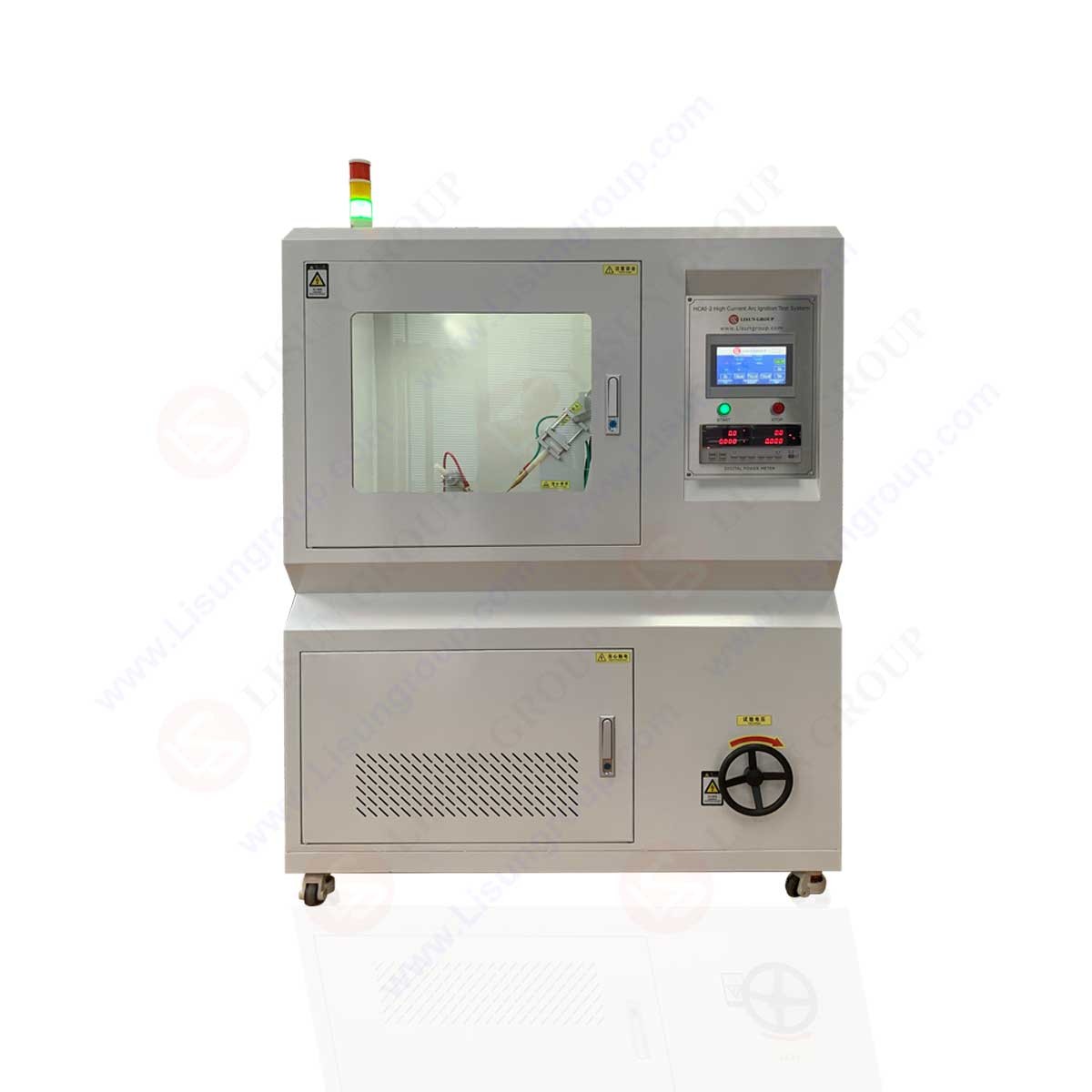
Schematic Diagram of Equipment Structure:
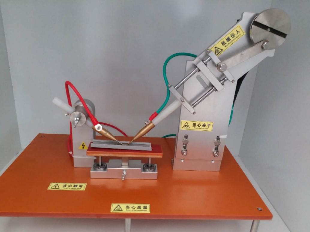
Images of the internal mechanisms:
Przegląd produktów:
Components made of insulating materials or other solid combustible materials inside electrical and electronic equipment—which can easily cause flames to spread—may ignite due to proximity to or contact with an electric arc, leading to electrical fires that endanger the normal operation of the equipment and personal safety. The High Current Arc Ignition Test System is designed and manufactured in accordance with standards such as IEC 60950, GB 4943, UL 746A, GB 4706, and GB/T 14048.1. It evaluates a sample’s resistance to ignition by high-current arcs based on whether the sample ignites after a specified number of arc-initiation cycles. It is suitable for research, production, and quality inspection departments of lighting equipment, low-voltage electrical appliances, household appliances, electrical and electronic products, and their components, as well as for industries dealing with insulating materials, engineering plastics, or other solid combustible materials.
1. Konfiguracja systemu
Fully automatic high-current ignition tester, PLC control system, 7-inch touchscreen, fan-assisted smoke extraction system, built-in LED lighting, 40A power meter, adjustable test power supply, and alarm function.
40A Power Meter: Displays current, voltage, power, frequency, and power factor in real time,
Test Power Supply: Current adjustable from 0 to 40 A; voltage adjustable from 125 to 250 V; power factor adjustable from 0.3 to 0.9
2. Dane techniczne
1. Electrode dimensions: φ3.2 mm to φ3.5 mm, 30° chisel tip (static electrode); φ3.0 mm, 60° tapered tip (moving electrode)
2. Electrode angle: 45° to the horizontal plane
3. Test voltage: 220 V
4. Arc-starting current: 33 ± 5% A (adjustable)
5. Power factor: COSφ 0.5 ± 0.05 (adjustable)
6. Arc-starting speed: 254 mm/s ± 25 mm/s
7. Arc-starting frequency: 40 times/min (adjustable)
8. Number of arc starts: 200 (configurable)
9. Specimen dimensions: 130 mm × 13 mm × (2–12) mm
10. Test Power Supply: 220 V, 10 kVA, 50 Hz
3. Steps to Follow
For safety reasons, be sure to install and use this equipment in accordance with the specified operating instructions!
1. Unlock the front and rear doors of the unit to inspect it (due to long-distance shipping, please be sure to inspect the unit before turning it on). Proceed to the next step only after confirming that the unit is in good working order;
2. Pull the power cord from the back of the unit and route it to the on-site power switch, such as a circuit breaker or air circuit breaker (rated power greater than 15 kW, single-phase AC voltage 220 V–230 V, frequency 50–60 Hz). Ensure the power cord is connected to the circuit breaker and that the wire ends are securely fastened. Before turning on the power, use a multimeter to verify that the power supply meets the equipment’s specifications. Only proceed if the measurement confirms compliance; otherwise, do not apply power, as this will burn out the equipment!
3. Open the rear door at the bottom of the unit, slide the two Schneider circuit breakers on the unit’s electrical control panel into the “ON” position, and the indicator light on the switching power supply inside the unit will illuminate. This indicates that the unit is now powered on; please be sure to exercise caution;
4. The “STOP” indicator light on the front of the device will turn red, indicating that the device is powered on but has not yet booted up. Please press the “START” button to boot the system. The touchscreen cursor will light up, and the message “Welcome” will appear immediately;
5. Open the glass door to the test laboratory to view the automated testing system used for testing:
On the left is the stainless steel electrode, which can rotate up and down to adjust its angle; on the right is the drive electrode, which consists primarily of a stepper motor, high-speed slide rails, and an eccentric cam that cause the electrode to move back and forth and up and down, thereby achieving reciprocating motion;
6. The sample holder is located between the two electrodes and can be adjusted up and down. Do not touch the sample holder during the test to prevent electric shock and mechanical injury. Cut the sample to the dimensions specified in the standard and place it on the sample holder;
7. Adjust the position of the electrode; if necessary, tap “Motor Jog” on the touchscreen interface.

The button allows the right-hand drive electrode to move slowly, so you can determine whether the sample is positioned correctly;
8. After setting up and calibrating the sample and electrodes, open the touchscreen control system, tap “Welcome,” and switch to the “Work Page”:

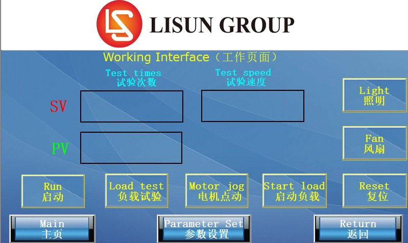
Number of tests: The number of times the arc was initiated by moving the electrode up and down while applying a current
Test Speed: The number of times the electrode moves up and down per minute (number of arc strikes per minute)
Start: Begin testing the starter motor; start counting and timing.
Load Test: Before performing the arc-starting test on the sample, the current, voltage, and power factor must be stabilized (by short-circuiting the electrodes to connect the load).
Motor Jog: Click “Motor Jog” to cause the drive electrode to move slowly (used when adjusting the contact angle between the electrode and the sample).
Start the load: Supply power to the load (turn on the Voltage Regulator)
Reset: Resets the current real-time parameters and actions (sets parameters to zero; resets button actions and shuts down the system)
Lighting: LED lights inside the cabinet
Fan: The exhaust fan inside the enclosure is used for ventilation (this fan is intended solely for ventilation and is not designed to exhaust smoke or fumes). (If smoke or fumes need to be exhausted, install an environmental smoke exhaust system 1 meter directly above the location where the equipment is placed; do not install it on the equipment itself.)
9. After calibrating the electrodes, navigate to the “Parameter Settings” page on the touchscreen:
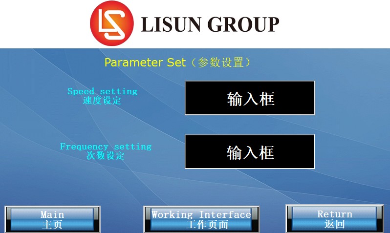
Speed Setting: Number of arc strikes per minute
Number of Trials: The total number of trials
10. On the Work page, click “Load Test.” The load is already turned on. Follow these steps to debug the load:
Click the “Start Load” button

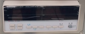
Turn on the power meter (press the power button)
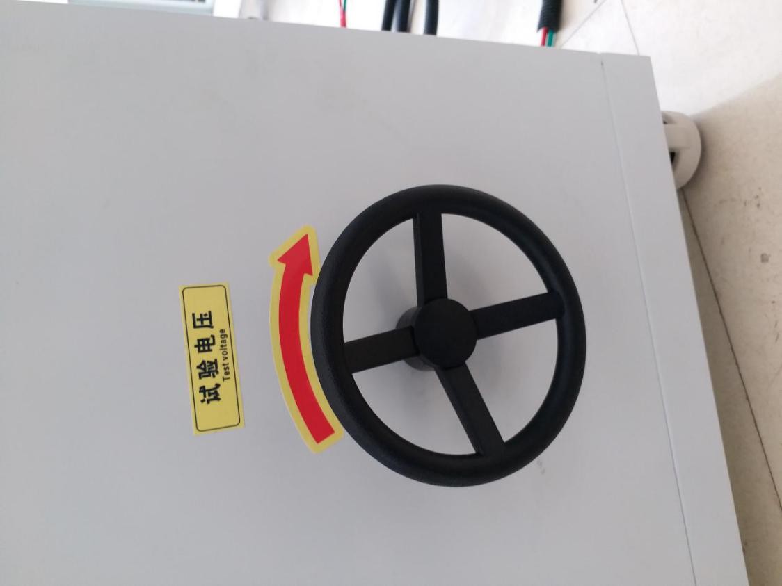
Slowly turn the handwheel on the test voltage control clockwise to adjust the voltage to 230 V.
Click “Load Test,” then set the power factor to 50% and the current to 32 A (try to complete the load test within one minute). High-current loads with low power factors can easily cause harmonics in the power grid.

Pay close attention to the power meter; do not exceed the current and voltage ranges for which the equipment is designed. Otherwise, the equipment will trigger an alarm, cut off power to the load, and the buzzer will emit a “beep-beep-beep” sound. You should immediately reduce the current and voltage.
After completing the load test, click “Cancel” to disable the load short-circuit function.

Click “Start” to begin the experiment,

(8) Electrical sparks may be emitted from the electrodes during the test.
4. List of Accessories
| Szczotka 1 | 1 sztuka |
| 2 Hex Wrenches | zestaw 1 |
| Przekaźniki 3 | zestaw 1 |
| 4. Laboratory Gloves | Par 2 |
| 5 Flat-head Screwdrivers | 1 sztuka |
| No. 6 Phillips screwdriver | 1 sztuka |